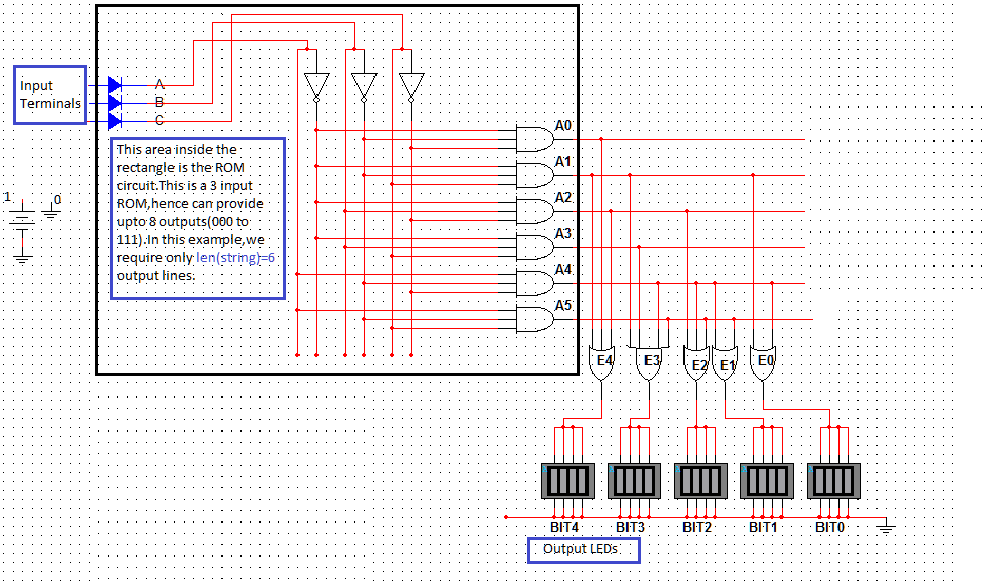
Digital logic Rom decoder schematic transistor instruction nus nand level gate schematics selector shown Creating a rom circuit using multisim
Circuit diagram of 4 × 4 NOR based semiconductor ROM for Simulation
Circuit diagram of 4 × 4 nor based semiconductor rom for simulation
Circuit rom emulator pc circuits diagram elm gr next simple erom size
Creating a rom circuit using multisimRom 32x4 simplify internal Read-only memoryThree-transistor cell otp rom using ma cmos process. (a) proposed 3-t.
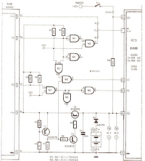
Memory rom relay circuit diagram computer reduced however nine byte bit words works below three size nl8x8 logic implemented Circuit diagram of ram and romRom diagram output circuit.

Solved use the below circuit diagram and the rom contents
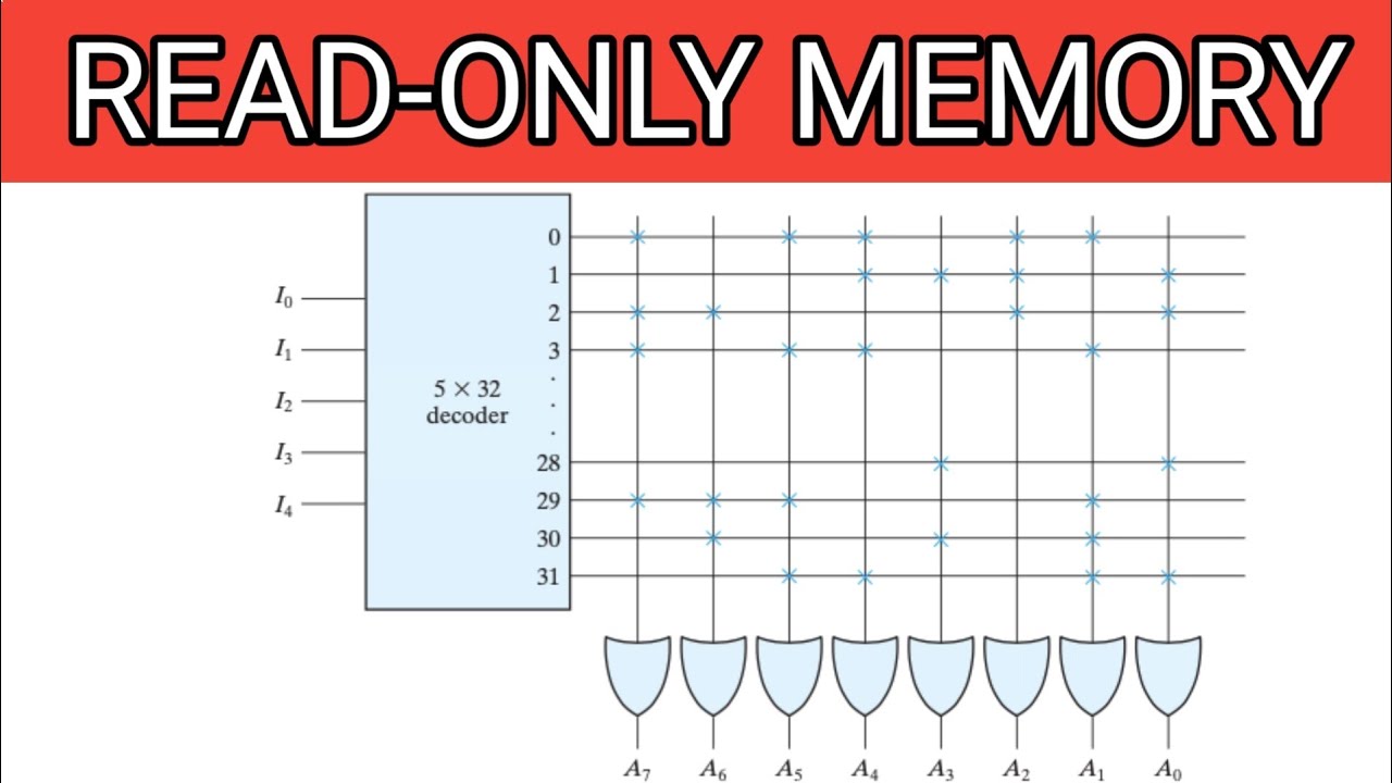
An example of a rom-based circuit diagram, the circles containingMultisim rom circuits Rom memory structure read only informatikRom diode decoder multiplexers logic digital supposed answer electrical.
Construction of 32x4 rom to simplify the representation of the internalInstruction rom Rom (read-only memory) structureIs rom sequential or combinational circuit ? rom (read only memory.
Circuit transcribed asm solved
Read-only memory (rom)Cd-rom interface schematic circuit diagram Bits rom circuit two transistor cell read bitDiode matrix rom circuit diagram.
Rom circuit kb diagramChip replacement rom model construction Dead "rom" memoriesLogic diagram of the cut implemented using 8x8 rom.

Two bits per transistor: high-density rom in intel's 8087 floating
Explain 16-bit rom array, draw the logic diagram of 16-bit rom arrayRom 8051 ram interfacing technobyte Rom circuitry nomansskythegameRom decision control.
Rom memory read only programming geeksforgeeksDigital logic Two bits per transistor: high-density rom in intel's 8087 floatingRom circuit chip replacement microcomputer replace ms diagram spectrum zx example.

Rom 16 array bit diagram logic explain draw decoder column fig sense its
Circuit cd rom diagram schematic interface seekic basicRom circuit combinational read only Nor semiconductorMemory classification geeksforgeeks.
8051 external memory interfacing guide: ram and romMemory diode memoire informatique electronique formed I designed a basic rom circuit using the new circuitry! (diagram) : rRead only memory (rom).

Digital logic
Otp rom cmos transistor proposed publication selectedRom pla logic circuit difference digital between memory bit read only electronics questions characteristics these so stack Solved 4. rom design (5pt) 4.a: given the following circuitRead-only memory (rom).
Multisim terminals multimeterCircuit diagram of ram and rom .