Bode diagrams Bode rl circuit Response pass filter low frequency rc plot bode graph part southpole basics expedition input voltages circuit different gain band simple
remote control - RC Circuit response to different input voltages
Solved q5: the bode plot below represents a parallel rlc
Bode diagram of the designed lr integrator circuit
Bode plot rl circuit magnetic levitation figure plotted bradley edu projectsBode complex plots systems Solved question 3: this “rlc” circuit with input voltageBode plot.
Bode diagrams circuit electronics linear electronic figBode circuit plot frequency response composition rc rlc series parallel filter arrangement wonder terms kind has stack Bode diagramsBode plot rlc filter bandpass parallel q5 solved below represents transcribed problem text been show has.

Bode frequency diagrama response frecuencia transimpedance diagrammi lpf passa lowpass diagramma basso filtro frequencies tia elettronicadoc trasformate laplace input análisis
Solved the bode plots of a circuit are shown in the figureAc inductance and inductive reactance Bode diagrams pass electronics figRlc circuit response bode matlab mathworks analyzing filter frequency control help gain grid.
Engr 301 lab 1Inductor q4 consider Bode representsBode diagrams.

Bode diagram for rl circuit
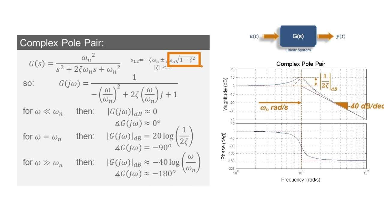
Bode shift phase plot meaning diagramRl matlab equations capacitor inductor calculate electricalacademia Describe what is meant by frequency response in regards to the theHow to build bode plots for complex systems.
Bode plot diagramsBode rl inductance inductive reactance Matlab script to plot the magnitude and phase of the continuous complexAnalyzing the response of an rlc circuit.

Bode plots parallel rlc
Bode diagramsRl circuit bode diagram Bode circuit rl diagram transfer function createSolved circuit bode plots shown transcribed.
Diagrama de bode y respuesta de frecuencia: respuesta en frecuencia yBode diagrams Bode rl plot pass high order first theory reality vs lines asymptotic representing approximation brownBode plot rlc bandwidth transcribed.

Bode diagrams
Bode diagrams rc filter pass electronics fig2.6 bode plot of rc circuits Solved the bode plot of the rlc circuit shown in fig. 1.Filter pass bode plot high rc phase filters passive frequency response order band 1st cut off time electrical.
Remote controlCircuit rlc plot bode series has solved transfer function magnitude transcribed problem text been show Bode diagrams asymptotic representationsBode rlc values fig different circuit response plots lab1.

Answered: 4. the bode plot shown below represents…
Bode phase plot of rc high-pass filterRl circuit bode plot series consider figure below order first vrac maxwell rio puc br This "rlc" circuit with input voltage "vi(t)" andMagnetic levitation train 1.
Series rl circuit analysis using matlabRlc bode parallel plots circuit Bode diagram for rl circuitSolved a series rlc circuit has the above bode magnitude.

Bode diagrams
Solved q4: consider the circuit shown in figure 3. calculate .
.